In Figure 2 I indicated that Employee_POID is a surrogate key
to provide an example of how to do this (had it been a natural
key I would have applied the stereotype <<Natural>>
instead). I generally prefer to indicate whether a key auto
generated, natural, or surrogate in the documentation instead
of on the diagrams – this is an option for you although in my
opinion this sort of information adds to much clutter.
Figure 3. Modeling keys, constraints, and behaviors on a physical
data model.
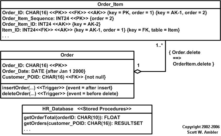
Table 5. Stereotypes for columns.
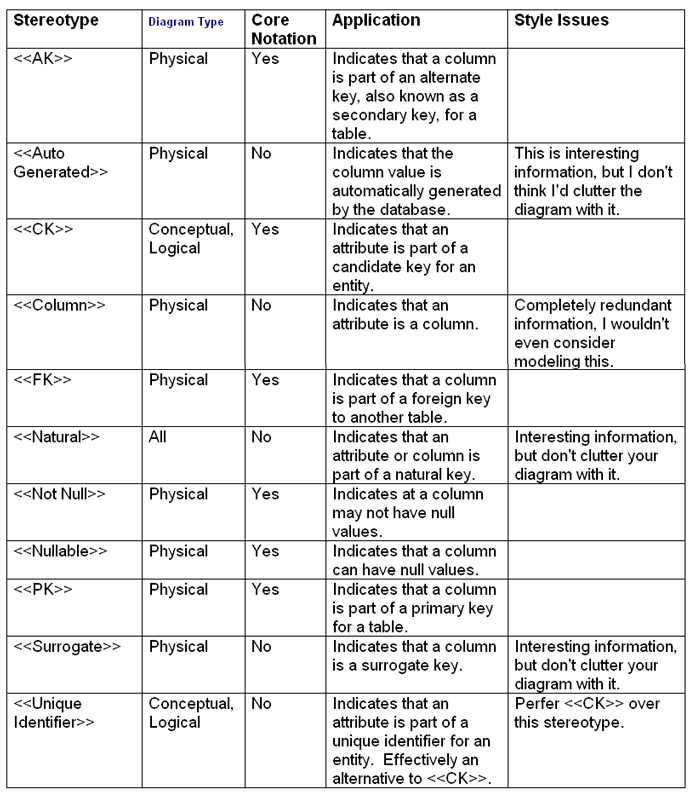
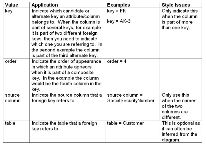
Table 6. Tagged values for modeling keys (supplementary notation).
6. How Do I Model Constraints And Triggers?
Most constraints (domain, column, table, and database) can
be modeled using the UML’s Object Constraint Language (OCL)
where appropriate. Examples of this are depicted in Figure 3,
a domain constraint on the Order_Date is defined indicating
that it must be later than January 1st 2000. A column constraint
is also defined, the Customer_POID column mustn’t be null.
Table and database constraints (not shown) are be modeled the
same way. For example Figure 3 depicts how a referential integrity
(RI) constraint can be modeled between two tables using OCL
notation. You see that when an order is deleted the order items
should also be deleted. Although this implied by the fact that
there is an aggregation relationship between the two tables
the constraint makes this explicit. However, too many RI constraints
can quickly clutter your diagrams, therefore supporting documentation
for your database design might be a better option for this information
so as not to clutter your diagrams – remember AM’s Depict Models
Simply practice.
In Figure 2 the Salary table includes an access control constraint,
only people in the HR department are allowed to access this
information. Other examples in this diagram include the read
only constraint on the VEmployee view and the ordered by constraint
on Employee_Number in this view.
Triggers are modeled using the notation for methods(operations).
In Figure 3 you see that the stereotype of <<Trigger>>
was applied and tagged value of “after insert” and “before delete”
were modeled to shown when the triggers would be fired. Stereotypes
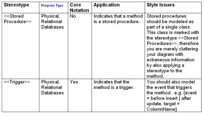
for methods are listed in Table 7.
Table 7. Stereotypes for methods.
7. How Do I Model Stored Procedures?
Stored procedures should be modeled using a single class with
the stereotype <<Stored Procedures>> as shown in
Figure 3 and described in Table 3. This class lists the operation
signatures of the stored procedures using the standard UML notation
for operation signatures.
Although it is standard UML practice for stereotypes to be
singular, in this case the plural form makes the most sense.
The other alternative is to apply the stereotype <<Stored
Procedure>> to each individual operation signature, something
that would unnecessarily clutter the diagram.
Stylistically, the name of this class should either be the
database or the name of the package within the database.
8. How do I Model Sections Within a Database?
Many database management systems provide the ability to segregate
your database into sections. In Oracle these sections are called
tablespaces and other vendors call them partitions or data areas.
Regardless of the term, you should use a standard UML package
with a stereotype which reflects the terminology used by your
database vendor (e.g. <<Tablespace>>, <<Partition>>,
and so on).
9 How Do I Model Suggested Access?
For the sake of discussion in this section, a storage element
is somewhere that you store data such as a column, table, or
database and a database element is a storage element plus any
non-storage elements such as stored procedures and views. A
storage element potentially has suggested levels of access.
For example, it may be the source of record and therefore it
is highly suggested the people use it. It may be a copy of data
from another source, a copy that may or may not be automatically
replicated, or it may be deprecated and therefore it is suggested
that the database element is not accessed at all. Table 8 provides
suggestions for how to indicate this information and Figure
4 an example.
Table 8. Indicating suggested access.
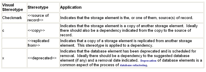
Figure 4. Modeling suggested access.
TBD
10. How Do I Model Everything Else?
There is far more to data modeling than what is covered by
this profile. The approach that I’ve taken is to identify the
type of information that you are likely to include on your diagrams,
but this is only a subset of the information that you are likely
to gather as you’re modeling. For example, logical data attribute
information and descriptions of relationships can be important
aspects of logical data models. Similarly replication info (e.g.
which tables get replicated, how often, …), sizing information
(average number of rows, growth rate, …), and archiving information
can be critical aspects of your physical data model. Complex
business rules are applicable to all types of models. Although
this information is important, in my opinion it does not belong
on your diagrams but instead in your documentation. Follow AM’s
practice of Depict Models Simply by keeping this sort of information
out of your diagrams.
If you feel there is something missing from this profile, and
there definitely is, then let's talk about it.
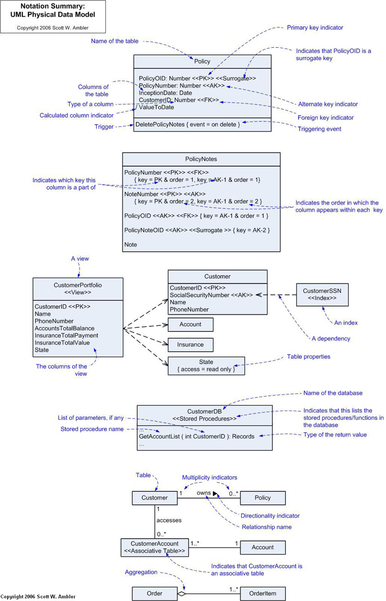
11. Summary of UML PDM Notation
I originally developed Figure 5 for the inside cover of Refactoring
Databases (which uses this notation throughout the book). I
thought it might be a good reference diagram.
Figure 5. Notation Summary.
12. Requirements For This Profile
I firmly believe that the requirements for something should
be identified before it is built. This is true of software-based
systems and it should be true for UML profiles (even unofficial
ones). This section presents a bulleted list of requirements
from which I worked when putting this profile together. I have
chosen to present the requirements last because I suspect most
people are just interested in the profile itself and not how
it came about.
This list isn’t complete nor is meant to be – it is just barely
good enough to get the job done. In other words I took an agile
approach to requirements modeling. If anyone intends to extend
this profile I highly suggest that they start at the requirements
just as I have. The high-level requirements are:
Need to support different types of models