| 编辑推荐: |
本文主要借号类图,类图的文件类、类图的关系,希望对您有所帮助。
本文来源于:ifi.uio.no,由火龙果软件Linda编辑,推荐。 |
|
Purpose
The class diagram (CD) describes the type of objects in a system and their static relationships. For each type of object, or class, in a CD, you can specify its characteristics (attributes) and the processes it can carry out (operations).
File type
In most cases, a diagram's file type matches its abbreviation. This is not true for the CD, which has a file type of cad. In OMT, the CD is a class association diagram (CAD).
Example class diagram
A sample class diagram.

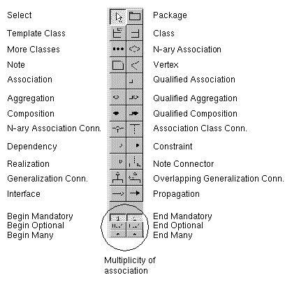
Control panel
The control panel of the class diagram.
Classes
Class
A class is a group of objects with similar properties (attributes), common behaviors (operations), common relationships to other objects, and common semantics. Most objects distinguish themselves through differences in their attribute values and relationships to other objects.
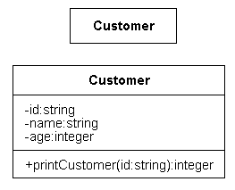
Folding a class hides its attributes and operations.
Label
The top text area contains the class name, the middle area defines the attributes, and the bottom area defines the operations.
Derived class
You can indicate a derived class by preceding the class name with a slash.
Attributes
Attributes describe an object's characteristics. Use this syntax to specify data attributes in the middle text area of the class symbol. Components within brackets ([]) are optional.
[+|#|-][ $ | / | *]attr-name:[data-type] [= initial-value][{attribute-changeability}]
Where, for the following options:
- visibility is one of the following:
- + indicates a public attribute
- # indicates a protected attribute
- - indicates a private attribute
- $ indicates a class (static) attribute--a value that applies to the entire class of objects, rather than to each instance.
- / indicates a derived attribute--a value that is the result of a computation.
- * indicates an attribute that must be part of the primary key. This information is meaningful only if your target language supports persistency. For more information, see The UML Suite Code Generation Guide for your target language.
- data-type is a standard type or a user-defined type. For more information, see The UML Suite Code Generation Guide for your target language.
- initial-value is the default value of the attribute.
- attribute-changeability specifies the changeability of the attribute. Valid options are:
- frozen indicates that there are no restrictions on modification.
- addOnly indicates that no links may be added after the creation of the source object.
Operations
Operations are the actions that can be carried out on or by the objects. (See also Propagation.) Use this syntax to specify operations in the bottom text area of the class symbol. Components within brackets ([]) are optional.
[visibility]operation-name[([parameter-kind] parameter-list)][:return-type][{property-string}]
Where, for the following options:
Class Definition Matrices (CDMs)
When you specify the first attribute or operation for a class, the UML suite creates a Class Definition Matrix (CDM) for the class. The CDM appears in the navigation and information areas of the Browser, but cannot be edited directly. When you open a CDM, the UML suite starts a class diagram editor, opening the class diagram that contains the class defined by the CDM. If the class appears in more than one class diagram, the UML suite prompts you to select the one that you want to open.
Associations
Association
Associations describe the relationships among objects. An association is a group of links in which each a link is a physical or conceptual connection between instances of an object. An association in a class diagram describes a set of potential links in the same way that a class describes a set of potential objects.
Label
Each association has five labels: an association name, multiplicity at both ends, and role names at both ends. A slash in front of the association name (/association-name) indicates a derived association.

Role names
You can specify a role name for each end of the association. If you specify role names at both ends, the association is bidirectional. If you specify a role names at only one end, the association is unidirectional.
The role name at the far end of an association describes the association from the perspective of the class at the near end. In the previous example, the rolename next to Class-B describes the association from Class-A to Class-B.
Interface specifier
A role name can include an interface specifier.
[visibility] role-name:interface-class-name
Where, for the following visibility options:
- + indicates a public operation
- # indicates a protected operation
- - indicates a private operation
Multiplicity
Specify multiplicity at both ends of the association. The multiplicity at the far end of an association specifies how many instances of the class at the far end of the association can relate to a single instance of the class at the near end of the association. In this example, each instance of class-A can be related to many instances of class-B; each instance of class-B must be related to exactly one instance of class-A.

The symbols in the control panel provide three multiplicity values: mandatory (1), optional (0..1), and many (*). After adding an association to the diagram, you can edit the multiplicities as needed. For example, you might edit a multiplicity value to indicate a multiplicity of 2 or more (2..*).

Qualified association
A qualified association is a one-to-many or many-to-many association in which the effective multiplicity is reduced by a qualifier.

Label
A qualified association has a mandatory qualifier. You specify the data type of the qualifier as a property of the qualified association. A qualified association also has the same five labels as an association: an association name, multiplicity at both ends, and role names at both ends. A slash in front of the association name (/association-name) indicates a derived association.
N-ary associations
Most associations between three or more classes are not true n-ary associations. You can usually decompose these apparent n-ary associations into more meaningful and correct binary associations or phrase them as qualified associations.
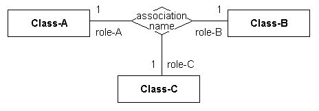
True n-ary associations represent associations between three or more classes. The n-ary association is an atomic unit and cannot be subdivided into binary associations without losing information.
Label
An n-ary has the same labels as an association. The association name is associated with the n-ary diamond. The multiplicity and role name at each end of each association is specified at the class-end of each association. A slash in front of the association name (/association-name) indicates a derived association.
Association class connector
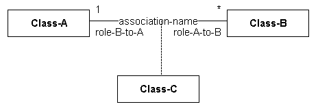
Graphically, an association class connector links a class to an association (including n-ary associations). Semantically, the association, the association class, and the association class connector are a single model element. The association has class-like properties, such as attributes, operations, and associations, which are defined by the association class.
How to draw an association
ÿ To draw an association:
- In the diagram, create the two classes involved in the association.
- In the control panel, select the multiplicity for the beginning of the association, the multiplicity for the end of the association, and the association symbol. For example, to create a one-to-many association, select the Begin Mandatory Association symbol, the End Many Association, and the Association symbol.
- Click the first class involved in the association, and then click the second class.
- If necessary, edit the multiplicities of the association.
How to draw an n-ary association
ÿ To draw an n-ary association:
- In the diagram, create the classes involved in the association.
- In the control panel, click the N-ary Association symbol button.
- Click in the diagram where you want to place the symbol.
- In the control panel, click the N-ary Connector symbol button.
- Click a class involved in the n-ary association, and then click the n-ary association symbol.
- Repeat step 5 for each class in the n-ary association.
How to insert an association class
ÿ To insert an association class connector:
- In the diagram, create the association and the association class.
- In the control panel, click the Association Class Connector symbol.
- Click the association, and then click the association class.
A dotted line between the association and the association class.
Aggregations and Compositions
Aggregation
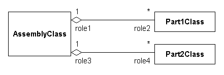
An aggregation is a relationship in which objects that represent the parts of a whole are associated with an object that represents the whole.
Label
Each aggregation has five labels: multiplicity at both ends, role names at both ends, and an aggregation name. See Associations for more information about multiplicity and role names.
Composition
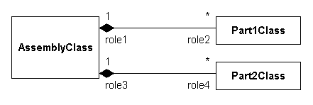
A composition is a special, strong form of an aggregation. As defined by Martin Fowler in his book UML Distilled, "With composition, the part object may belong to only one whole; further, the parts are usually expected to live and die with the whole."
Label
Each composition has five labels: multiplicity at both ends, role names at both ends, and a composition name. See Associations for more information about multiplicity and role names.
Compared with association
Aggregation and composition are both special, strong forms of association. If two objects are bound tightly by a part-whole relationship, you show the relationship as an aggregation. If two objects are usually considered as independent, even though they may often be linked, you show the relationship as an association.
Aggregation and composition add semantic connotations in certain cases. An aggregate or composite object is made of components. Components are part of the whole. Significant properties of aggregation and composition are transitivity, antisymmetry, and propagation.
Qualified aggregation
A qualified aggregation is a one-to-many or many-to-many aggregation in which the effective multiplicity is reduced by a qualifier.

Label
A qualified aggregation has a mandatory qualifier. You specify the data type of the qualifier as a property of the qualified aggregation. A qualified aggregation also has four labels: multiplicity at both ends and role names at both ends. See Associations for more information about multiplicity and role names.
Qualified composition
A qualified composition is a one-to-many or many-to-many composition in which the effective multiplicity is reduced by a qualifier.

Label
A qualified composition has a mandatory qualifier. You specify the data type of the qualifier as a property of the qualified composition. A qualified composition also has four labels: multiplicity at both ends and role names at both ends. See Associations for more information about multiplicity and role names.
Class Hierarchies
Generalization
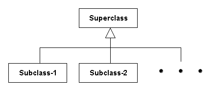
Classes are arranged into hierarchies. A generalization is the relationship between a class and one or more refined versions of the class. The class being refined is the superclass; each refined version is a subclass. Each subclass inherits all the features of its superclass, but adds its own attributes and operations.
Generalization is sometimes called the is-a relationship, because each instance of a subclass is also an instance of the superclass. A generalization describes an association between one independent class and several dependent classes; the independent class, which is the superclass, is a sort of largest common denominator of the various subclasses that are associated with it. Generalization is a powerful tool for sharing similarities among classes while preserving their differences.
Label
discriminator
The discriminator, an attribute whose value differenctiates between subclasses, is optional.
Two types of generalization
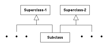
The UML suite supports two types of generalization: disjoint and overlapping. A class can inherit from more than one class hierarchy or from more than one subclass in an overlapping generalization, but cannot inherit from two subclasses in the same disjoint generalization.
Disjoint
A generalization is disjoint when a concrete class must inherit from exactly one subclass.

Overlapping
A generalization is overlapping when a concrete class can inherit from more than one subclass.
More classes
A more-classes symbol (three dots) indicates that additional classes exist, but are not shown.
Label
No label.
How to draw a generalization
ÿ To draw a generalization:
- In the diagram, create the classes involved in the hierarchy.
- In the control panel, click the Generalization or Overlapping Generalization symbol button.
- Click in the superclass, and then in the subclass.
the UML suite draws the first leg of the generalization.
- Click in the triangle of the generalization, and then in the next subclass.
the UML suite draws the second leg of the generalization.
Interfaces
Interface class
An interface class is a class that has operations, but no attributes. You do not implement the operations of an interface class. A class that implements the interface implements each of the operations defined in the interface class. In other words, the interface class provides no method bodies for the operations it defines; the class that implements the interface provides method bodies for each of the operations defined in the interface.
In the UML suite, use the Stereotype property to assign the interface stereotype to the class. See Editing Property Values.

Label
See Classes.
Ways to indicate implementation
The UML suite provides two ways to indicate that a class implements an interface:
- Interface (or lollipop) symbol
- Realization
Interface symbol
You can use the Interface symbol to indicate that a class implements an interface. You attach the symbol to the class that implements the interface. In this example, the DataInputStream class implements the DataInput interface.

Label
Label the symbol with the name of the interface class.
Realization symbol
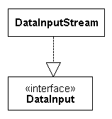
You can use the Realization symbol to indicate that a class implements an interface. You draw the realization from the class that implements the interface to the interface. In this example, the DataInputStream class implements the DataInput interface.
Label
No label.
Templates
Purpose
Use a template class to declare a set of classes that have different types, but all have the same behavior. You declare the template class, and its attributes and its operations, then instantiate the individual classes based on the template class.
Use a template class only to create a set of classes that have exactly the same behavior. If changing the class type changes the behavior of an operation, use a class hierarchy rather than a template.
Template class
The template class and class symbols are similar. The template class has a dashed rectangle in the upper right corner in which you specify a set of formal parameters. When you instantiate a class based on the template, you specify a set of actual arguments. The instantiated class is a copy of the template class, where the formal parameters are replaced by the actual arguments.
Template classes can have attributes, operations, and connections to classes (associations, aggregations, compositions, and so on).
Label
See Classes.
Template parameters
You can specify one or more formal parameters on a template class. Multiple parameters can be separated by commas or by carriage returns (placed one per line). Each parameter must be one of the following:
- The formal name of a classifier; for example, a class name. When specifying attributes and operations for the template class, you can use this parameter wherever a type is expected; for example, as the type of an attribute.
- A formal constant followed by a colon and standard type; for example, age:integer. When specifying attributes and operations for the template class, you can use this parameter wherever a constant is expected; for example, as the initial value of an attribute or the size of an array.
How to instantiate a class
ÿ To instantiate a class based on a template class:
- Add a class symbol for the class to be instantiated.
- Draw a dependency from the class to the template class.
- Add the <<bind>> stereotype to the dependency.
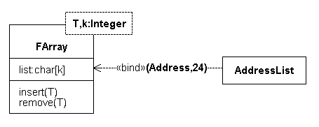
- After the <<bind>> stereotype, in parentheses and separated by commas, specify the actual types and constants to be used in place of the formal parameters specified on the template class. Quoted strings and decimal numbers are considered to be constant values; all other values are considered to be types.
Example
The FArray template class is used to instantiate the AddressList class.
Note: Not all code generators support array specifications. For more information, see The UML Suite Code Generation Guide for your target language.
Dependencies, Constraints, and Propagation
Dependency
Dependencies indicate where changing an object may force other objects to be changed as well. Class-B is dependent on Class-A. If you change Class-A, you may also have to change Class-B.

Label
No label, unless you are using the <<bind>> stereotype to instantiate a class based on a template class (see Templates).
Constraint
Constraints restrict the relationship between two classes, two associations, or a class and an association. (In this context, an association can be an association, a qualified association, an aggregation, a qualified aggregation, a composition, or a qualified composition.)

Label
{constraint-description}
Propagation
Propagation applies one or more operations to an associated object when the operation is applied to the starting object. In this example, applying operation on Class-A causes the same operation to be carried out on Class-B.

Place the propagation symbol on or near a connector (associations, qualified associations, compositions, qualified compositions, aggregations, and qualified aggregations). You can move the propagation symbol during insertion, to prevent it from overlapping its connector. When you move a connector, attached propagation symbols move with it.
Label
operation[, operation[, ...]]
Packages
Package
A package groups classes (and other objects) into higher-level units. In the UML suite, a package implements a system. The package name is, therefore, the name of a system in the current phase.
A package symbol represents an entire system. You do not use the diagram to define the content of the system, but rather the use of the system. The objects defined in the system are the content of the system.

Interfaces
A package can implement an interface, which you represent using either a CD Interface or Realization symbol. See Interfaces.
Hierarchies
Packages, like classes, can be arranged hierarchically. You represent this using the Generalization symbols. See Class Hierarchies.
Dependencies
Packages, like classes, can have dependencies. You can represent this using the Dependency symbol. See Dependencies, Constraints, and Propagation.
Patterns
Purpose
Patterns allow you to represent an abstract idea that solves a recurring problem. The pattern does not contain the idea or explain the idea in any great depth. the UML suite provides two pattern mechanisms:
- Design pattern
- Design pattern connector
Design pattern
The design pattern is a symbol containing one label, the pattern's name. Design Patterns exist within both Class Diagrams and Collaboration Diagrams (see Patterns) but serve slightly different purposes in each diagram.
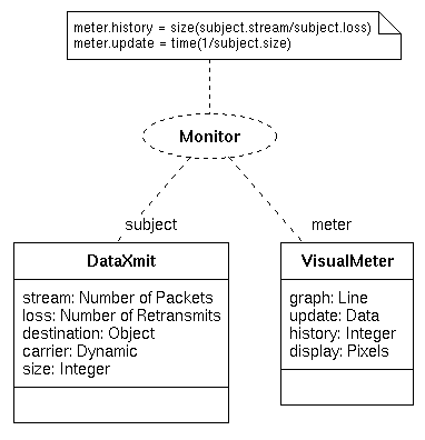
In a Class Diagram, a pattern serves as a role for the class or template class to which it is connected. By contrast, Collaboration Diagrams further define a design pattern's role.
UML does not contain all aspects of patterns, but you can include material based on one of the two schools of thought on design patterns.
Label
One, closest to the design pattern and available through the Design pattern connector.
Design pattern connector
The design pattern connector provides relevance to a design pattern by connecting a design pattern to an object. Design pattern connectors provide one label, located near the design pattern.
Design pattern connectors have no properties.
| 