Purpose
The sequence diagram (SD) specifies the time and control
aspects of a system. Typically, you use the SD to analyze
only the more complex business events. Simple business
events rarely require an SD.
Compared with a collaboration diagram
A collaboration diagram shows the objects and relationships
involved in an interaction. It shows the messages exchanged
among the objects during the interaction, numbering
them to show the sequence of messages. It does not show
the timing of the messages.
File type
In most cases, a diagram's file type matches its abbreviation.
This is not true for the SD, which has a file type of
etd. In OMT, the SD is an event trace diagram (ETD).
Definitions
Events are actions between the objects in your project.
They can also transmit data.
A scenario is the sequence of events during one execution
of a program. A scenario can include all the events
or only the events sent to or received by certain objects
in the system. An SD can contain more than one scenario.
For example, you might create an SD that provides two
scenarios for placing a customer order: one for an existing
customer and the other for a new customer.
Example SD
This SD shows a simple scenario for the use of an automatic
teller machine. In this scenario, the system rejects
the card. For the customer this transaction is simple:
he inserts the card and the card is rejected. For the
system, several actions are necessary. A constraint
specifies 10 seconds as the maximum acceptable time
interval for the transaction.
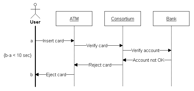
This sequence is fairly general; you can work out the
Insert Card event more completely by including details
such as entering the personal identification number
and requesting the type of transaction. The analyst
must decide what level of detail to use in the SDs.
Control panel
The control panel for the sequence diagram.
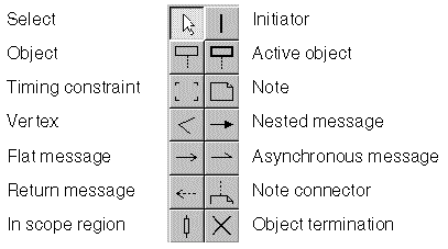
Initiators and Objects
Initiator
The initiator starts the sequence. Each sequence can
only have one initiator, but you can draw more than
one sequence in a diagram. The initiator represents
an external agent, such as a user, that interacts with
the system. It can be a class, but does not have to
be.
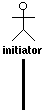
Label
name
Object
An object is an instance of a class. The object line
represents a portion of the lifetime of an object in
the system. Time flows from top to bottom on the symbol.
The spacing between event symbols is not important.
It does not indicate the length of time between events.
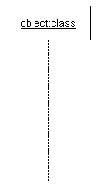
Label
name[:type]
The type must be a class defined in a class diagram.
If you omit type, the UML suite assumes the class name
is the same as the object name.
Active object
An active object, also known as a concurrent object,
owns a thread of control and can initiate control activity.
For example, processes and tasks are active objects.
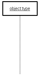
Label
name[:type]
The type of an active object does not have to be defined
in a class diagram. If you omit type, the UML suite
assumes type is the same as name.
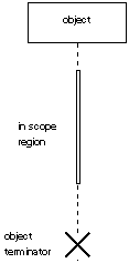
In Scope region
The In Scope region is a white rectangle that can be
placed on top of an initiator, object, or active object
to show that the object is in scope. You can move the
In Scope region up and down the axis of the object,
but not away from it. When you move the In Scope region,
nearby messages move with it. When you move messages,
the In Scope region does not move. This allows you to
move messages from one In Scope region to another.

Label
No label.
Object terminator
The object termination symbol represents the destruction
of the object.
Label
No label.
Messages
Messages
A message represents an individual stimulus from one
object to another. A message can signal an event or
transmit data. It occurs at a point in time.
Multiple messages can be sent from the same point on
the initiator or object line; that is, sent at the same
point in time. An object can send a message to itself.
Such a message must arrive at the object at another
point in time.
Label
Each message has three labels:
- A message name with this syntax:
- [condition]message-name[(parameter[,parameter,...])]
- condition is an optional boolean expression
that must be enclosed in square brackets
- message-name is the message name.
- parameter is an optional argument.
- Two timing marks, one at either end of the message.
Timing marks are optional. You generally use them
in combination with timing constraints to document
the time interval between two or more messages,
as shown in
Example SD.
Flat message
The Flat Message symbol is a stick arrowhead. It shows
the progression to the next step in a sequence.

Nested message
The Nested Message symbol is a filled solid arrowhead.
It represents a procedure call or other nested flow
of control. The nested sequence is completed before
the outer level sequence resumes.

Asynchronous message
The Asynchronous Message symbol is a half stick arrowhead.
It shows an asynchronous message between two objects.

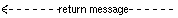
Return message
A return message is a message that an object returns
as a result of a process initiated by a message flow.
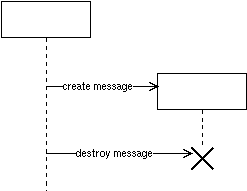
Create / Destroy messages
A create message is a message drawn to the name of
an object.
A destroy message is a message drawn to an object terminator.
Timing Constraints
Timing constraint
Timing constraints are text blocks used to document
the time interval between two timing marks, as shown
in
Example SD.
How to insert a timing mark
Timing marks are labels at the beginning and end of
each message.
ÿ To insert a timing mark:
- Move your cursor to the end of the message, and
to the opposite side of the connecting object line.
- When the text cursor appears, enter the timing mark.
How to insert a timing constraint
ÿ To insert a timing constraint:
- In the control panel, click the text block tool.

- Click in the drawing area where you want to place
the text block. A small square appears indicating
the location of the timing constraint.
- Move the cursor just below and to the right of the
square. An I-bar appears indicating that you can enter
text.

- Enter the text of the timing constraint. The text
replaces the small square.
How to move a timing constraint
ÿ To move a timing constraint, drag it from one
location to another using either both mouse buttons
(Windows) or the middle mouse button (UNIX).
|