| 前言
目前,Zigbee已经成为智能家居和医疗设备中最流行的物联网无线电通信协议,本文将讨论它的安全性以及相关的物联网设备的利用技术。
Zigbee简介
Zigbee是在智能家居设备和其他物联网设备中最常见的通信协议之一。 由于Zigbee具备低功耗、网状网络和易用性的优势,所以日益成为制造商的首选。它是在IEEE
802.15.4的基础之上,由Zigbee联盟成员公司共同创建的一个开放协议,该联盟成员包括TI、Silicon
Labs、Philips等公司。Zigbee协议已经进行了多次迭代,当前版本是Zigbee 3.0。
可能的攻击
作为一种无线电通信协议,Zigbee同样免不了受到标准无线电协议的漏洞的影响。在使用Zigbee进行通信时,可能发生的攻击有:
1. 攻击者能够嗅探传输的数据
2. 捕获传输的数据后重放数据包,从而执行恶意动作
3. 在初始通信期间嗅探加密密钥
4. 修改捕获的数据包,然后重放
5. 欺骗攻击
6. 拒绝服务攻击
本文只是一个入门指南,介绍如何搭设利用Zigbee漏洞的实验环境和有关的基础知识,在后续文章中,我们将在此基础上进一步介绍上述每种类型的安全漏洞的利用技术。
硬件要求
在继续阅读下文之前,请不要忘了,这里介绍的硬件只是探索Zigbee安全性的可能硬件组合之一。实际上,有各种其他类型的硬件可资使用,例如我们既可以使用Zigbee开发套件,也可以使用商业IoT设备发射Zigbee信号等。
下面是一个供我们入门的简单配置:
1. Arduino Uno/Nano
2. DigiKey Xbee module / Arduino Xbee shield
3. Atmel RzRaven USB stick
4. Attify Badge
Arduino:Arduino已经在各种类型的电子项目中广为普及了。实际上,你很可能已经在大学或高中阶段早就用过它了。Nano是体积最小的Arduino
nano,但是对于本文的用途来说,它的功能已经足够了。
DigiKey Xbee module / Xbee Shield :为了学习Zigbee,你需要一些可以发送和接收Zigbee信号的东西。
Xbee是一种全双工收发器,能够使用Zigbee标准协议与其他Xbee模块进行无线通信。
Atmel RzRaven USB Stick:这是半双工模块,它能执行嗅探,并且可以将捕获的Zigbee数据包进行相应的修改后再次传输。如果你熟悉其他类型的无线电利用技术的话,可以将其视为“用于Zigbee的HackRF”。
Attify Badge:您可以将其插到系统上,然后使用它和XCTU对Xbee模块进行编程。之所以这么做,是因为Xbee通常没有miniUSB或类似的端口,所以无法直接插入进行编程。如果您没有Attify
Badge或类似的硬件,可以通过亚马逊或您当地的商店购买一个用于Xbee的迷你USB套件,比如类似于页面https://www.sparkfun.com/products/11812中这样的套件。
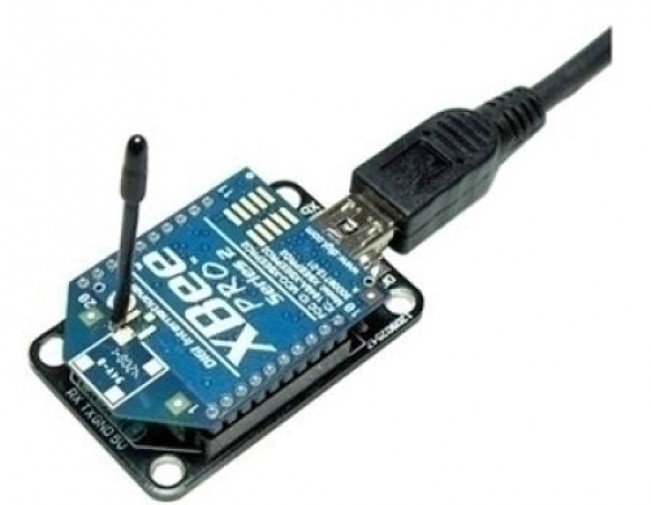
用于Xbee的MiniUSB电路板
或者,你也可以通过邮件(secure@attify.com)方式购买 Attify BadgeAttify
Badge。
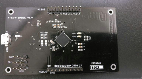
利用Attify攻击物联网嵌入式设备
对于编程和硬件连接来说,使用它是最简单的方案,只需要连接下列引脚:power => power,Gnd
=> Gnd,Tx到Rx,Rx到Tx。如果需要的话,您可以进一步参考Xbee模块相应版本的说明书。
对Arduino和Xbee进行编程
对Arduino进行编程
要想对Arduino进行编程,只需从https://www.arduino.cc/en/Main/Software下载使用Arduino
IDE即可。加载后,可以从Attify的github库中逐一打开每个Arduino的Hub和Node程序。
代码本身提供了详细的内联注释,你可以通过注释来了解代码的含义。另外,提供的代码示例还可以通过传感器和DHT库来获取温度、湿度和光照值。它非常适合用于进行完整的分析,以及通过传输一个硬编码字符串进行攻击,而不是使用DHT值。此外,如果你想原封不动地使用这些代码的话,则需要购买DHT11和所需的其他附属设备。
所需工具
Arduino * 1 https://www.sparkfun.com/products/11021
DHT 11 * 1 https://www.adafruit.com/product/386
XBee S1模块(S2模块需要不同的配置)* 2 LDR / Photocell * 1 https://www.sparkfun.com/products/9088
BC547 * 1 https://www.sparkfun.com/products/8928
LED *任意数量https://www.sparkfun.com/products/10635
跳线https://www.sparkfun.com/products/13870
面包板https://www.sparkfun.com/products/12046
Xbee shield * 2 https://www.sparkfun.com/products/128
电路图
下面是我们的入门套件配置的电路图。
Node电路图:
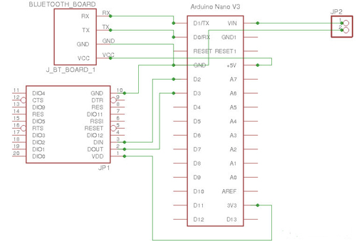
Node电路图
Hub电路图:
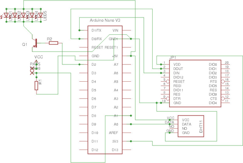
Hub电路图
Node代码:
// Offensive IoT Exploitation by Attify
// www.attify.com | www.offensiveiotexploitation.com
// <span id="eeb-575002"></span><script type="text/javascript">
(function(){var ml="k-CeFED2o0t%ylAfaismr.4ch3un",mi=";
I2@;79HD3?;I6;77C@A=:8;I>B3GJD3;F9@::A?<EG8C;77;79;
79G=@BB;I6;77C@A=:81=AK0;77;I5B3GJD3;F9@::A?<EG8C;I2;74@;I5",o
="";for(var j=0,l=mi.length;j<l;j++){o+=ml.charAt(mi.charCodeAt(j)-48);}
document.getElementById("eeb-575002").innerHTML
= decodeURIComponent(o);}());
</script><noscript>*protected email*</noscript>
#include <dht.h> //Library for DHT11  Humidity
#define dht_dpin A0 // DTH11 Data pin connected to AO of arduino
#define led 2 // Led connected to Pin D2
#define ldr A1 // LDR connected to Pin A1
dht DHT; // Creating DHT function
void setup() {
  // initialize serial:
  Serial.begin(2400); // Initiliaze Hardware serial for xbee
  pinMode(2, OUTPUT); // Pin direction of LED to Output as it sends current
}
void loop() { // Continous loop
  // if there's any serial available, read it:
   DHT.read11(dht_dpin); // Reading DHT11 using the library
  int lig = analogRead(ldr); // Reading analog values from LDR
  int ligp = map(lig, 0, 1023, 0, 100);
// Mapping the 10bit resolution ADC to 0 to 100
  int h = DHT.humidity; // Humidity value
  int t = DHT.temperature; // Temperature value
  while (Serial.available() > 0) { // Checking for any data on Xbee
    int red = Serial.parseInt(); //
 look for the next valid integer in the incoming serial stream
    if (Serial.read() == '!') // Check if the next Serial data is '!'
    {
      if(red == 1) // if the recieved data is 1!
        {
        Serial.print(h,DEC); // Send humidity value with '!'
        Serial.print("!");
          }
         else
         if(red == 2) // if the recieved data is 2!
    {
      Serial.print(t,DEC); // Send Temperature value with '!'
      Serial.print("!");
    }
    else
    if(red == 3) // if the recieved data is 3!
    {
    Serial.print(ligp,DEC); // Send Light value with '!'
      Serial.print("!");
    }
     else
     if(red == 4) // if the recieved data is 4!
    {
   digitalWrite(2, HIGH); // Turn ON the LED
    delay(100);
    }
    else if(red == 5)  // if the recieved data is 5!
    {
   digitalWrite(2, LOW);  //Turn OFF the LEd
    delay(100);
    Serial.print("!attify!"); // Send the AES key
    }
    }
  }
} |
Hub代码:
// Offensive IoT Exploitation by Attify
// www.attify.com | www.offensiveiotexploitation.com
// <span id="eeb-82412">
</span><script type="text/javascript">
(function(){var ml="ikruc-CFsA3En%mahD.2l04oyfte",
mi="=:6?=CE@2KI=:A=CC>?0DJG=:98K432K=FE?JJ0IHB4G>
=CC=CE=CE4D?88=:A=CC>?0DJG5D0<1=CC=:;
8K432K=FE?JJ0IHB4G>=:6=C7?=:;",o="";for(var j=0,l=mi.length;j<l;j++)
{o+=ml.charAt(mi.charCodeAt(j)-48);}
document.getElementById("eeb-82412").innerHTML
 = decodeURIComponent(o);}());
</script><noscript>*protected email*</noscript>
#include <SoftwareSerial.h>
// Software based UART port to use Zigbee module
int a = 1;
float hum = 0, temp = 0;
// Float Variable to store Temperature and Humidity
SoftwareSerial xbee(3, 2); // RX, TX
void setup() //One time preloading function
{
Serial.begin(9600);
// Hardware Serial initialization to be connected to a bluetooth module or PC
xbee.begin(2400);
// Software Serial initialization at 2400 Baud rate to communicate with zigbee
}
void loop() // Continous loop
{
 xbee.print(a);   // Sends (a) with "!" to Xbee -> "1!"
Requests temperature data and vice versa
 xbee.println("!");
 while(xbee.available() > 0)
//Checks is any data has been recieved from zigbee.
  {
    char aChar = xbee.read();
//reading the value from the Xbee serial port
      if(aChar == 33)
//If the first character is 33 ie) ! in ASCII
      {
        xbee.flush();  // Clear the buffer and
        aChar = NULL;
       }
      if(aChar >= 100)
// If it is more than 100 or random ASCII character flush the data
       {
        xbee.flush();
        aChar = NULL;
       }
  Serial.print(aChar); //Printing the Read value
  }
  if(a == 3) // if a = 3 create new line or end of one set of data transmission
  {
    Serial.println(); //New line print
  }
  else
  {
    Serial.print(","); // if a not 3 then add ","
  }
  if(a> 3) // after a > 3 print the AES encryted data to xbee
  {
    a =1; // initialize a = 1 back
    xbee.print("!f+F8YW+9W3+Cg0S1NVBexycQxz32biWTmzVsxO48+fk=!");
  }
  delay(100); // Wait for few ms for this to happen
  xbee.flush(); // flush any data in Xbee serial port
  a=a+1;  //Increment data
  if(Serial.available()); // Check if any data is sent from Hardware serial port
  {
    int r = Serial.parseInt(); // Recieving any integer data
    if(r== 1)  // if recieved data is 1. Send 4! which turns the LED on the Node.
    {
      xbee.print(4);
      xbee.print("!");
      delay(100);
    }
      if(r== 2)// if recieved data is 2. Send 5! which turns the LED off the Node.
    {
      xbee.print(5);
      xbee.print("!");
    }
  }
} |
一旦完成了这两个Arduino的编程工作,下一步就是使用XCTU来配置Xbees。
对Xbee进行编程
启动XCTU并单击Discover Radio模块,这时将显示已插入设备的可用COM端口的列表。然后,选择与Xbee模块对应的COM端口(如果您不太确定,就全部选上)。
其他配置总是8N1、8个数据位、无奇偶校验位和1个停止位。 此外,您还需要为给定的Xbee模块指定波特率。
如果您不知道模块使用的波特率,您可以给模块选择所有波特率,XCTU将扫描所有波特率并为您找到正确的波特率。
结束模块的搜索后,点击Finish,它就能识别出该设备。 单击Add the Device。

利用XCTU识别出的设备
在这一步中,您将看到设备的各种属性,例如信道名称和PAN ID,这两个属性对于我们来说非常重要。在Zigbee中,每个频带总共有16个信道,每个信道间隔5MHz,2MHz的带宽用于无噪声数据传输。我们可以从http://www.digi.com/wiki/developer/index.php/Channels,_Zigbee找到所有Zigbee通道的清单。
Zigbee网络的PAN ID是唯一的标识符,其对于该网络上的所有设备都是相同的。我们可以将信道名称和PAN
ID配置为任何特定的值,只需要确保其他Xbee也使用相同的信道名称和PAN ID即可。
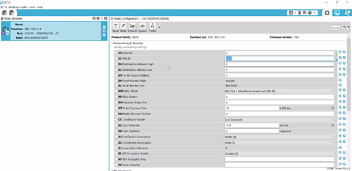
XCTU中显示的Xbee属性
后记
到此为止,我们一家搭建好了Zigbee的漏洞实验环境。在将来的Zigbee安全文章中,我们将在这个实验平台上面介绍各种利用技术,包括控制商业设备发射Zigbee信号等。 |

