| ±ύΦ≠ΆΤΦω: |
±ΨΈΡœξœΗΫι…ήΝΥ5GΜυ±ΨΆχ¬γΫαΙΙΘ§œΒΆ≥…ηΦΤ‘≠‘ρ,
…ηΦΤΒΡΙΠΡή ΒΧε,…ηΦΤΒΡΫ”ΩΎ“‘ΦΑ5G–≠“ι’Μ,œΘΆϊΕ‘ΡζΒΡ―ßœΑ”–ΥυΑο÷ζΓΘ
±ΨΈΡά¥Ή‘”ΎΦρ ιΘ§”…ΜπΝζΙϊ»μΦΰAlice±ύΦ≠ΆΤΦωΓΘ |
|
“ΜΓΔΜυ±ΨΆχ¬γΫαΙΙ
1.1 ’ϊΧεΦήΙΙ
5GœΒΆ≥”…Ϋ”»κΆχΘ®ANΘ©ΚΆΚΥ–ΡΆχΘ®5GCΘ©Ήι≥…Θ®38.300Θ©ΓΘ»τΩΦ¬«NSAΘ®Ζ«ΕάΝΔΉιΆχΘ©≥ΓΨΑΘ§‘ρΜΙ–η“ΣΩΦ¬«4GΒΡΆχ‘ΣΓΘ

ΆΦ1ΘΚOverall Architecture
AN”–ΝΫ÷÷ΘΚ
gNB, ΈΣUEΧαΙ©NR”ΟΜßΟφΚΆΩΊ÷ΤΟφ–≠“ι÷’ΫαΒψΓΘ
ng-eNB, ΈΣUEΧαΙ©E-UTRAΒΡ”ΟΜßΟφΚΆΩΊ÷ΤΟφ–≠“ιΒΡ÷’ΫαΒψΓΘ
1.2 Άχ‘ΣΜυ±ΨΙΠΡή
ΗςΆχ‘ΣΙΠΡήœξœΗΟη ωΧΪ≥ΛΘ§ΨΏΧεΦϊ3gpp 38.300Θ§¥σ÷¬ΙΠΡή»γœ¬ΆΦΘΚ
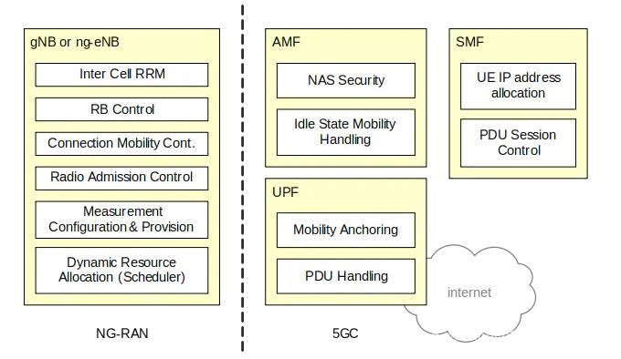
ΆΦ2ΘΚFunctional Split between NG-RAN
and 5GC
1.3 ANΆχ¬γΫαΙΙΘ®38.401Θ©
ΟΩΗω¬ΏΦ≠gNB ”…“ΜΗωgNB-CUΚΆ»τΗ…ΗωgNB-DUΉι≥…ΓΘΟΩΗωgNB-CUΚΆgNB-DUΆ®ΙΐF1¬ΏΦ≠Ϋ”ΩΎΝ§Ϋ”ΓΘ

ΆΦ3ΘΚgNB Overall architecture
“ΜΑψά¥ΥΒ“ΜΗωgNB-DU÷ΜΝ§Ϋ”“ΜΗωgNB-CUΓΘΒΪ «ΈΣΝΥ Βœ÷ΒΡΝιΜν–‘Θ§ΟΩΗωgNB-DU“≤Ω…ΡήΝ§Ϋ”ΒΫΕύΗωgNB-CUΓΘ
“ΜΗωgNB CU÷–ΒΡΩΊ÷ΤΟφΚΆ”ΟΜßΟφ «Ζ÷άκΓΘ“ΜΑψ÷Μ”–“ΜΗωCPΘ§ΒΪ «‘ –μ”–ΕύΗωUPΓΘ“ΣΉΔ“βΒΡ «Θ§gNB-CUΦΑΝ§Ϋ”ΒΡ»τΗ…gNB-DUΉςΈΣ“ΜΗω’ϊΧε¬ΏΦ≠gNBΕ‘Άβ≥ œ÷ΒΡΘ§÷ΜΕ‘ΤδΥϊΒΡgNBΚΆΥυœύΝ§ΒΡ5GCΩ…ΦϊΓΘ

ΆΦ4ΘΚOverall architecture for separation
of gNB-CU-CP and gNB-CU-UP
3GPPΗχΝΥ“Μ÷÷≤ΈΩΦΒΡΆχ‘Σ≤Ω πΖΫ ΫΓΘΩΦ¬«ΒΫΝΥgNBΦδΒΡXNΝ§Ϋ”Θ§“‘ΦΑ”κΚΥ–ΡΆχΒΡNGΝ§Ϋ”ΓΘ

ΆΦ4ΘΚExample deployment of an Logical
gNB/en-gNB
ΕΰΓΔœΒΆ≥ΫαΙΙΘ®23.501Θ©
2.1 œΒΆ≥…ηΦΤ‘≠‘ρ
5GœΒΆ≥ΫαΙΙ≤…”ΟNFV/SDN“‘÷ß≥÷ ΐΨίΝ§Ϋ”ΚΆ“ΒΈώΝιΜν≤Ω π, ¥Ό ΙΜυ”Ύ“ΒΈώΒΡΩΊ÷ΤΟφΆχ¬γΙΠΡήΚΆΗ≈ΡνΜΞΕ·:
”ΟΜßΟφΙΠΡήΚΆΩΊ÷ΤΟφΙΠΡήΖ÷άκ, ‘ –μΕάΝΔΒΡΩ…ά©’Ι–‘,Ω…―ίΫχ–‘ΦΑΩ…ΝιΜν≤Ω π.±»»γΩ…―Γ‘ώ≤…”ΟΦ·÷– ΫΜρ’ΏΖ÷≤Φ ΫΒΡΖΫ Ϋ.
ΙΠΡή…ηΦΤΡΘΩιΜ·, ±»»γ≤…”ΟΝιΜνΗΏ–ßΒΡΆχ¬γ«–Τ§.
Έό¬έ‘Ύ ≤ϥºΖΫ ”Ο,ΕΦΩ…“‘ΫΪœύ”ΠΒΡΙΐ≥Χ(Άχ¬γΙΠΡή÷°ΦδΒΡΜΞΕ·)Ε®“εΈΣ“ΒΈώ, “‘±ψΩ…“‘Η¥”ΟΥϊΟ«.
»γΙϊ”––η“ΣΕΦΩ…“‘ Ιœύ”ΠΒΡΆχ¬γΙΠΡήΚΆΤδΥϊΒΡNFΜΞΕ·. 5GΫαΙΙ≤ΔΟΜ”–≈≈≥ΐ÷–ΦδΙΠΡήΑο÷ζ¬Ζ”…ΩΊ÷ΤΟφ–≈œΔ.
(±»»γ DRA).
Υθ–ΓΫ”»κΆχ¬γ(AN)ΚΆΚΥ–ΡΆχ¬γ(CN)ΒΡ“άάΒ–‘.’βΗωΫαΙΙ «“ΜΗωΙΪΙ≤Ϋ”»κΆχANΝ§Ϋ”ΜψΨέΒΡΚΥ–ΡΆχ. ΕχANΩ…“‘ «≤ΜΆ§ΒΡΫ”»κάύ–Ά±»»γ3GPPΫ”»κΆχΚΆnon-3GPPΫ”»κΆχ.
÷ß≥÷Ά≥“ΜΒΡΦχ»ΪΦήΙΙ.
÷ß≥÷ ΓΑstatelessΓ± Άχ¬γΙΠΡήNF, ’β–©Άχ¬γΙΠΡήΒΡΦΤΥψΉ ‘¥ΚΆ¥φ¥ΔΉ ‘¥Ϋβών.
÷ß≥÷ΡήΝΠΩΣΖ≈
Ά§ ±÷ß≥÷±ΨΒΊΚΆΦ·÷–Μ·ΒΡ“ΒΈώ. ΈΣΝΥ÷ß≥÷ΒΆ―”≥Ό“ΒΈώ≤ΔΖΟΈ ±ΨΒΊ ΐΨίΆχ¬γ,”ΟΜßΟφΙΠΡή≤Ω π–η“ΣΨΓΩ…ΡήΒΡΩΩΫϋΫι»κΆχ¬γAN.
‘ΎVPLMN÷ß≥÷Μυ”ΎLBOΚΆΙι τΒΊ¬Ζ”…ΒΡ¬ΰ”ΈΖΫ Ϋ.
2.2 …ηΦΤΒΡΙΠΡή ΒΧε
5GœΒΆ≥ΫαΙΙΕ®“εΝΥ»γœ¬Άχ‘ΣΙΠΡή ΒΧε (NF)ΘΚ
UE: ”ΟΜß÷’ΕΥ…η±ΗUser Equipment (UE)
RAN: Ϋ”»κΆχ¬γ(Radio) Access Network (RAN)
AMF: Ϋ”»κΦΑ“ΤΕ·–‘ΙήάμΙΠΡήAccess and Mobility Management Function
UPF: ”ΟΜßΟφΙΠΡήUser plane Function (UPF)
AUSF: Φχ»®ΖΰΈώΙΠΡήAuthentication Server Function
DN: ΐΨίΆχ¬γData Network (DN), ±»»γ‘Υ”Σ…Χ“ΒΈώΘ§ΜΞΝΣΆχΫ”»κΜρ’ΏΒΎ»ΐΖΫ“ΒΈώΒ»ΓΘ
UDFS: Ζ«ΫαΙΙ–‘ ΐΨί¥φ¥ΔΙΠΡήUnstructured Data Storage Function
NEF: Άχ¬γ“ΒΈώ≥ œ÷ΙΠΡήNetwork Exposure Function (NEF)
NRF: Άχ‘Σ ΐΨί≤÷ΩβΙΠΡήNF Repository Function (NRF)
NSSF: Άχ¬γ«–Τ§―Γ‘ώΙΠΡήNetwork SliceSelection Function (NSSF)
PCF: ≤Ώ¬‘ΩΊ÷ΤΙΠΡήPolicy Control function (PCF)
SMF: Ϋχ≥ΧΙήάμΙΠΡήSession Management Function (SMF)
UDM: Ά≥“Μ ΐΨίΙήάμΙΠΡήUnified Data Management (UDM)
UDR: Ά≥“Μ ΐΨί≤÷ΩβΙΠΡήUnified Data Repository (UDR)
AF: ”Π”Ο≤ψΙΠΡήApplication Function (AF)
EIR: 5G…η±Η±ξ ΕΉΔ≤α…η±Η5G-Equipment Identity Register (5G-EIR)
2.3 …ηΦΤΒΡΫ”ΩΎ
2.3.1 Μυ”Ύ“ΒΈώservice-basedΘ§ΩΊ÷ΤΟφœύΙΊΒΡΆχ‘ΣΙΠΡή ΒΧεΡήΙΜ Ύ»®ΤδΥϊΆχ‘Σά¥ΖΟΈ ΥϋΒΡ“ΒΈώΓΘ
5GœΒΆ≥ΫαΙΙ÷–ΑϋΚ§»γœ¬Μυ”Ύ“ΒΈώservice-basedΒΡΫ”ΩΎ
Namf: Service-basedinterface exhibited by AMF.
Nsmf: Service-basedinterface exhibited by SMF.
Nnef: Service-basedinterface exhibited by NEF.
Npcf: Service-basedinterface exhibited by PCF.
Nudm: Service-basedinterface exhibited by UDM.
Naf: Service-basedinterface exhibited by AF.
Nnrf: Service-basedinterface exhibited by NRF.
Nnssf: Service-basedinterface exhibited by NSSF.
Nausf: Service-basedinterface exhibited by AUSF.
Nudr: Service-basedinterface exhibited by UDR.
Nudsf: Service-based interfaceexhibited by UDSF.
N5g-eir: Service-based interface exhibited by 5G-EIR.
2.3.2 Μυ”Ύ≤ΈΩΦΒψreference point Θ§ΒψΕ‘ΒψΆχ‘ΣΙΠΡή“ΒΈώ÷°ΦδΜΞΉς”ΟΒψΓΘ
5GΫαΙΙ÷–Ε®“εΝΥ»γœ¬≤ΈΩΦΒψΘΚ
N1: Referencepoint between the UE and the AMF.
N2: Referencepoint between the ?AN and the AMF.
N3: Referencepoint between the ?AN and the UPF.
N4: Referencepoint between the SMF and the UPF.
N6: Referencepoint between the UPF and a Data Network.
N9: Referencepoint between two UPFs.
N5: Referencepoint between the PCF and an AF.
N7: Referencepoint between the SMF and the PCF.
N8: Referencepoint between the UDMand the AMF.
N10: Referencepoint between the UDM and the SMF.
N11: Reference point between the AMF andthe SMF.
N12: Reference point between AMF andAUSF.
N13: Reference point between the UDM andAuthentication
Server function the AUSF.
N14: Reference point between two AMFs.
N15: Referencepoint between the PCF and the AMF in
case of non-roaming scenario, PCF in thevisited network
and AMF in case of roaming scenario.
N16: Reference point between two SMFs,(in roaming
case between SMF in the visited network and the SMF
in the homenetwork).
N17: Referencepoint between AMF and 5G-EIR.
N18: Referencepoint between any NF and UDSF.
N22: Reference pointbetween AMF and NSSF.
N24: Referencepoint between the PCF in the visited
network and the PCF in the home network.
N27: Reference pointbetween NRF in the visited network
and the NRF in the home network.
2.3.3 œΒΆ≥ΫαΙΙ
Ζ«¬ΰ”Έ«ιΩωœ¬Μυ”Ύ“ΒΈώΫ”ΩΎΒΡ5GœΒΆ≥ΫαΙΙΆΦ

Ζ«¬ΰ”Έ«ιΩωœ¬ Ι”Ο≤ΈΩΦΒψΒΡ5GœΒΆ≥ΫαΙΙΆΦ»γœ¬Θ§¥ΥΆΦ’Ιœ÷Άχ‘ΣΙΠΡή÷°ΦδœύΜΞΉς”ΟΓΘΚΆΤδΥϊ¥ΪΆ≥ΒΡΖδΈ―“ΤΕ·Άχ¬γΫαΙΙάμΫβΥΦ¬ΖάύΥΤΓΘ

Ζ«¬ΰ”ΈΧθΦΰœ¬UE Ι”ΟΕύΗωPDU SessionΆ§ ±Ϋ”»κΝΫΗω ΐΨίΆχ¬γΒΡ«ιΩωΓΘ¥ΥΆΦ Ι”Ο≤ΈΩΦΒψά¥’Ι ΨΝΥΈΣΕύΗωPDU
Session―Γ”ΟΝΫΗωSMFΒΡ≥ΓΨΑΓΘ‘Ύ’β÷÷«ιΩωœ¬ΟΩΗωSMF“≤ΡήΙΜΈΣ“ΜΗωPDU Sessionά¥ΩΊ÷ΤlocalΚΆcentralΒΡUPFΓΘ

Ζ«¬ΰ”Έ≥ΓΨΑœ¬ Ι”ΟΒΞ“ΜPDU sessionΆ§ ±Ϋ”»κΝΫΗω ΐΨίΆχ¬γ (local
andcentral)ΒΡΫαΙΙΓΘ

¬ΰ”Έ≥ΓΨΑΒΡœΒΆ≥ΆΦΚήΕύΘ§“≤ΚήΗ¥‘”Θ§œξΦϊ23.501
Ζ«3gppΫ”»κΒΡΩ¥“ΜΗωΆΦΘ§ΤδΥϊ«ιΩωœξΦϊ23.501

5GCΚΆEPCΜΞ≤ΌΉςΒΡΫαΙΙΘ§Ω¥“Μœ¬Ζ«¬ΰ”Έ≥ΓΨΑΘ§ΤδΥϊ≥ΓΨΑΦϊ23.501

»ΐΓΔ–≠“ι’Μ
3.1 5G-ANΚΆ5GCΒΡΫ”ΩΎ(N2)
NG-AP–≠“ιΕ®“ε‘Ύ38.413÷–Θ§SCTP–≠“ιΕ®“ε‘ΎRFC 4960ΓΘ


N2-SMœϊœΔ «NG-APœϊœΔΒΡ“Μ≤ΩΖ÷Θ§’β≤ΩΖ÷œϊœΔ”…AMFΗΚ‘πΆΗ¥ΪΓΘ¥”Ϋ”»κΆχΒΡΫ«Ε»N2-SMœϊœΔ÷’Ϋα”ΎAMFΓΘ
3.2 XNΫ”ΩΎ


3.3 Ω’ΩΎ


3.4 UEΚΆ5GCΫ”ΩΎ
N1 NAS–≈ΝνΒΡ÷’ΫαΒψΈΣUEΚΆAMFΘ§“ΜΗωNAS–≈ΝνΝ§Ϋ””Ο”ΎΉΔ≤αΙήάμ/Ν§Ϋ”Ιήάμ(RM/CM)ΚΆΜαΜΑΙήάμΘ®SMΘ©ΓΘNAS–≠“ι”…NAS-MMΚΆNAS-SMΝΫ≤ΩΖ÷Ήι≥…ΘΜ¥ΥΆβUEΚΆ5GCΦδΜΙ”–ΕύΗωΤδΥϋ–≠“ιΘ®SMΓΔSMSΓΔUE
policyΓΔLCSΒ»Θ©Θ§’βΕΦ–≠“ιΕΦ «Ά®ΙΐN1 NAS-MMΫχ––ΆΗ¥ΪΒΡΓΘ
RM/CM NASœϊœΔΚΆΤδΥϋάύ–ΆΒΡNASœϊœΔ «ΫβώνΒΡΘ§“≤ΨΆ «AMFΗΚ‘πRM/CMΘ§ΤδΥϋΒΡœϊœΔΨΆΆΗ¥ΪΗχΕ‘”ΠΒΡΡΘΩι»Ξ¥ΠάμΓΘ
ΈΜ”ΎAMFΒΡNAS-MMΗΚ‘πΘΚ
1Θ©Έ§ΜΛ¥ΠάμRM/CMΒΡΉ¥Χ§ΚΆΕ‘”ΠΝς≥Χ¥ΠάμΘ§
2Θ©ΧαΙ©Α≤»ΪΒΡNASœϊœΔ¥Ϊ δΆ®ΒάΘ®“≤Φ¥NAS≤ψΒΡΦ”ΟήΚΆΆξ±ΘΘ©Θ§
3Θ©ΆΗ¥ΪΤδΥϋάύ–ΆΒΡNASœϊœΔΘ®SMΓΔSMSΓΔUE PolicyΓΔLCSΘ©ΓΘ
»γΙϊUEΆ§ ±Ά®Ιΐ3GPPΚΆnon-3GPPΫ”»κΆχΫ”»κ5GCΘ§Ρ«Ο¥ΟΩΗωΫ”»κΡΘ Ϋœ¬ΕΦ”–“ΜΗωN1
NAS–≈ΝνΝ§Ϋ”ΓΘ

3.4.1 UEΓΣAMF

NAS-MM: NAS-MM–≠“ιΗΚ‘πΉΔ≤αΙήάμΓΔΝ§Ϋ”ΙήάμΓΔ”ΟΜßΟφΝ§Ϋ”ΒΡΦΛΜνΚΆ»ΞΦΛΜν≤ΌΉςΘ§ΗΚ‘πNASœϊœΔΒΡΦ”ΟήΚΆΆξ±ΘΓΘ5G
NAS–≠“ιΕ®“ε‘Ύ TS 24.501.
5G-AN Protocol layer: Ϋ”»κΆχΒΡ–≠“ι’Μ»ΓΨω”ΎΨΏΧεΒΡΫ”»κΆχάύ–ΆΘΜ»γΙϊ¥”eNBΫ”»κΘ§‘ρΕ‘”ΠΒΡΩ’ΩΎ–≠“ι’ΜΕ®“ε‘ΎTS36.300Θ§»γΙϊ¥”gNodeBΫ”»κΘ§‘ρΕ‘”ΠΒΡΩ’ΩΎ–≠“ιΕ®“ε‘ΎTS38.300Θ§»γΙϊ¥”non-3GPPΆχ¬γΫ”»κΘ§‘ρΕ‘”ΠΒΡ–≠“ι’ΜΕ®“ε‘ΎTS23.501
8.2.4’¬ΫΎΓΘ
3.4.2 UEΓΣSM

NAS-SM: NAS-SMœϊœΔ÷ß≥÷”ΟΜßΟφPDUΜαΜΑΒΡΫ®ΝΔΓΔ–όΗΡΓΔ ΆΖ≈ΘΜNAS-SMœϊœΔΆ®ΙΐAMF¥Ϊ δΘ§«“ΤδΕ‘AMF «ΆΗΟςΒΡΘ®“≤ΨΆ «AMFΗΚ‘πΆΗ¥ΪSMœϊœΔΓΔ≤ΜΕ‘ΤδΫχ––ΫβΈω¥ΠάμΘ©ΓΘΨΏΧεΒΡœϊœΔΚΆΝς≥ΧΦϊ”Ύ–≠“ιTS
24.501ΓΘ
3.4.2 UE PDUΜαΜΑΒΡ”ΟΜßΟφ–≠“ι’Μ

N3ΩΎ Ι”ΟGTP-U–≠“ιΘ§’βΚΆ3G/4G“Μ―υΘ§GTP-UΕ®“ε”ΎTS29.281ΘΜ5G-AN”ΟΜßΟφ–≠“ι’Μ»ΓΨω”ΎΨΏΧεΒΡΫ”»κΆχάύ–ΆΓΘ
3.5 F1Ϋ”ΩΎ–≠“ι

3.6 non-3GPPΫ”»κ


IKEv2Φϊ”ΎRFC7296ΓΕInternet Key Exchange Protocol Version
2ΓΖ
3.7 5GCΓΣ5GC
5GCΡΎ≤ΩΆχ‘Σ÷°ΦδΒΡΫ”ΩΎΈΣSBIΫ”ΩΎΘ§≤…”ΟHTTPΖΰΈώΒΡ–Έ ΫΓΘSBIΫ”ΩΎ”–ΘΚNamf,
Nsmf, Nudm, Nnrf, Nnssf, Nausf, Nnef, Nsmsf, Nudr,
Npcf, N5g-eir, NlmfΓΘ

…œΆΦΨΆ «SBI–≠“ι’ΜΘ®ΆΦΤ§ά¥‘¥TS29.500 5.1’¬ΫΎΘ©Θ§≤…”ΟΜΞΝΣΆχ≥Θ”ΟΒΡHTTP/TCP–≠“ιΘ§HTTP/2«κ≤ΈΩΦRFC
7540ΓΘ
|